High resolution seismic reflection data sets have been acquired internationally for both academic and commercial purposes in many different offshore environments.
This includes:
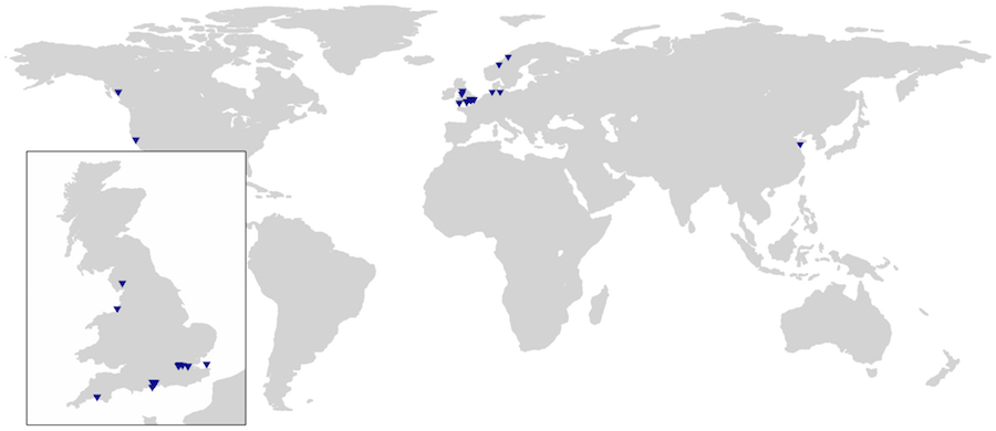
Below is a map of project sites and locations where 3D Chirp data have been acquired so far:
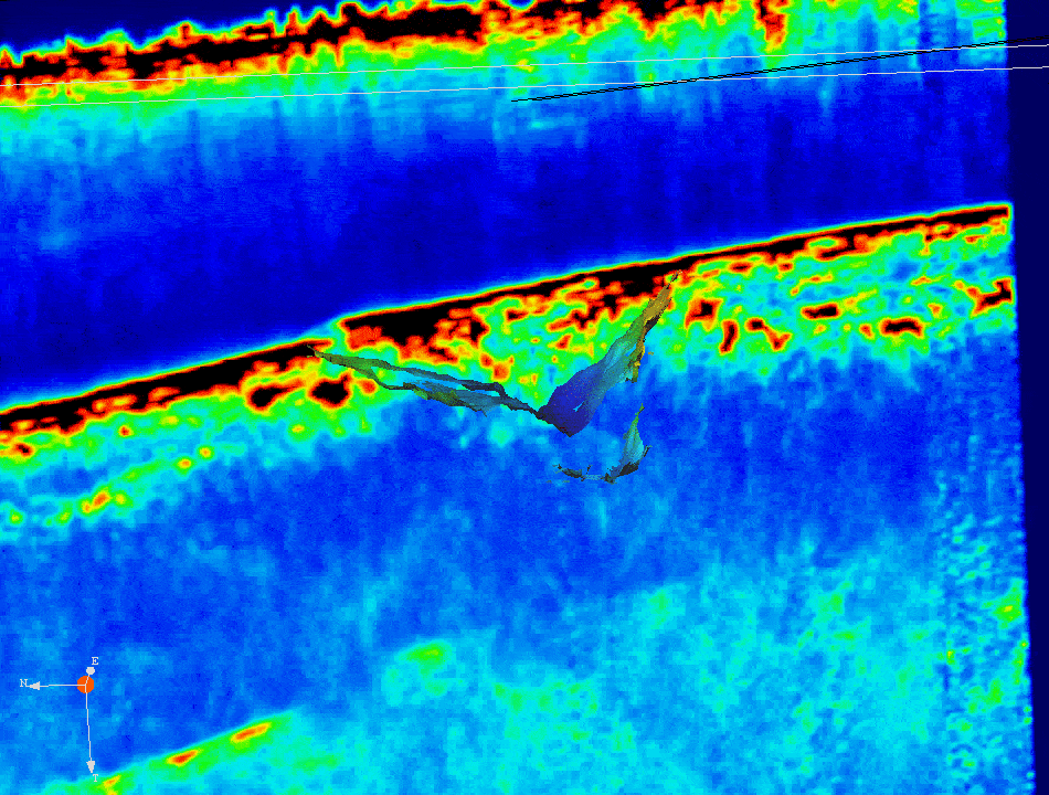
A landslide in 1996 near Finneidfjord, Norway initiated a submarine landslide. Failure initiated offshore but propagated inland by 100-150 m causing extensive damage to a local highway. Approximately 1 x 10⁶ m3 of sediment was displaced in total, producing a deposit 0.3 – 0.4 m thick.
A large multidisciplinary data set was acquired to probe the morphology and internal structure of the landslide and evaluate the cause of the complex failure. This included 2D and 3D seismic data along with high-resolution swath bathymetry and multiple sediment cores up to 14 m depth with in situ and laboratory measurements of rock properties.
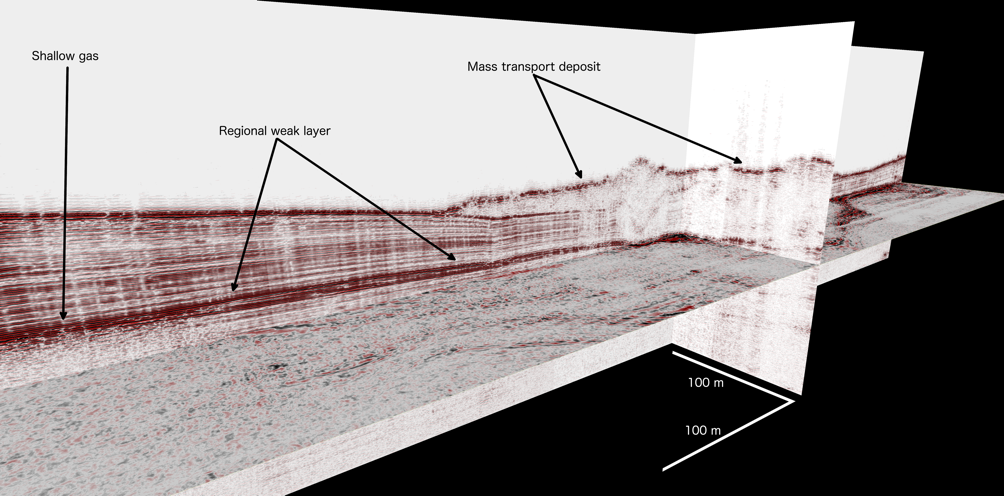
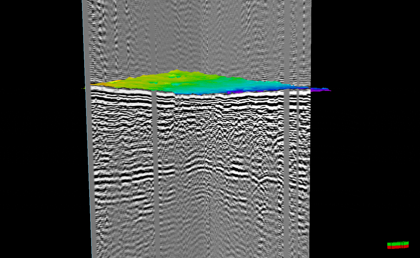
The 3D Chirp was used to image a targeted 150 m x 1100 m area, providing exceptional delineation of high-amplitude, composite reflections for water depths of 50 – 60 m and very minimal processing. The data were also pre-stack Kirchhoff time migrated onto a 12.5 x 12.5 cm mid- point grid using the frequency-approximated algorithm of Vardy and Henstock (2010) (Figure 1), revealing a geologically complex weak layer thought to influence local slope stability.
Inversion of these broadband seismic data allowed the calculation of remote physical properties (using acoustic quality factor, Q). This permitted a depth and spatial assessment of the relationship between morphology and grain size that was correlated against the high-resolution geotechnical data, identifying the slide plane as a weak, laminated, clay-rich bed.
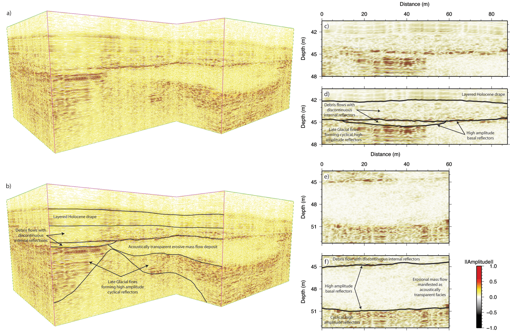
Windermere is a glacially overdeepened lake located in the southeastern Lake District, UK. Using the 3D Chirp sub-bottom profiler, mass movement deposits related to the Younger Dryas (YD) are imaged, documenting their internal structure and interaction with preexisting deposits in unprecedented detail. Three distinct flow events are identified and mapped throughout the 3D survey area. Package structures and seismic attributes classify them as: a small (total volume of c. 1500 m3) debris flow containing deformed translated blocks; a large (inferred total volume of c. 500,000 m3), homogeneous fine-grained mass flow deposit; and a debris flow (inferred total volume of c. 60,000 m3) containing small (c. 8.0 x 2.0 m) deformed translated blocks.
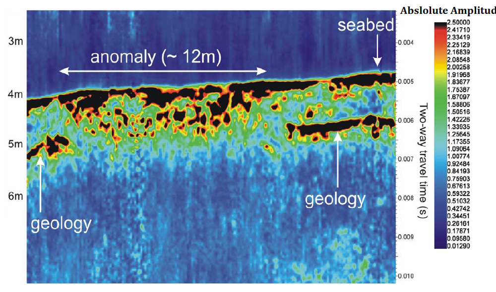
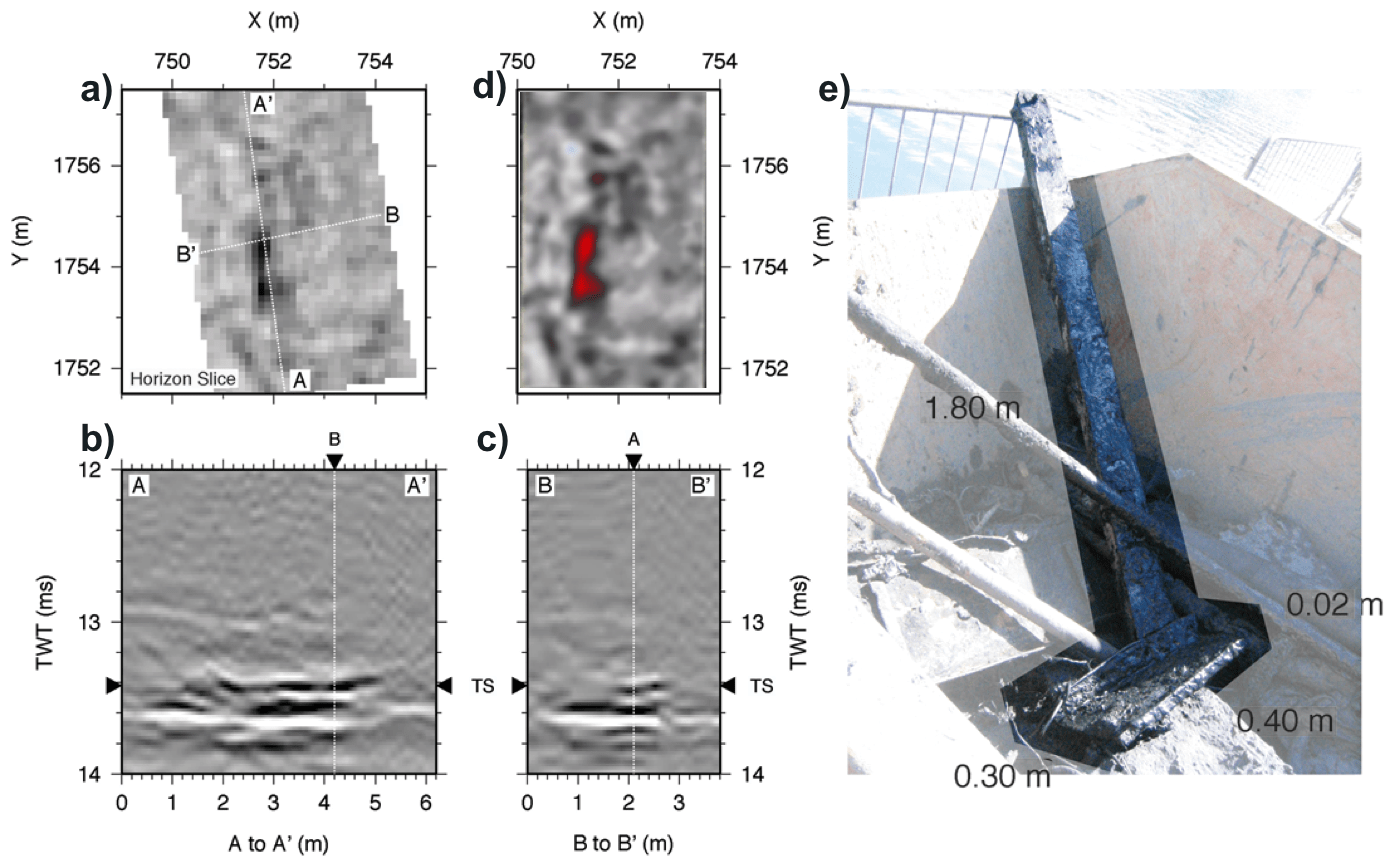
An atidal basin on the southern coast of England was surveyed to map bedrock protrusions and the size and distribution of buried objects. The study area of 150 x 250 m provided a series of unique challenges, including a large number of discrete objects ranging from tens of centimeters to several meters in size, buried in a thin veneer 0.5 to 1.5 m of unconsolidated silt overlaying a flat bedrock surface that showed high acoustic contrast and short wavelength roughness. By comparing comprehensive post-survey dredging of the entire site with a prestack time-migrated 3D volume, it is possible to confirm a 100% detection rate for all discrete buried objects larger than 0.30 x 0.30 m in an illuminated area.
Results presented in Vardy et al (2008). A movie of the data volume in Figure 1 can be downloaded here.
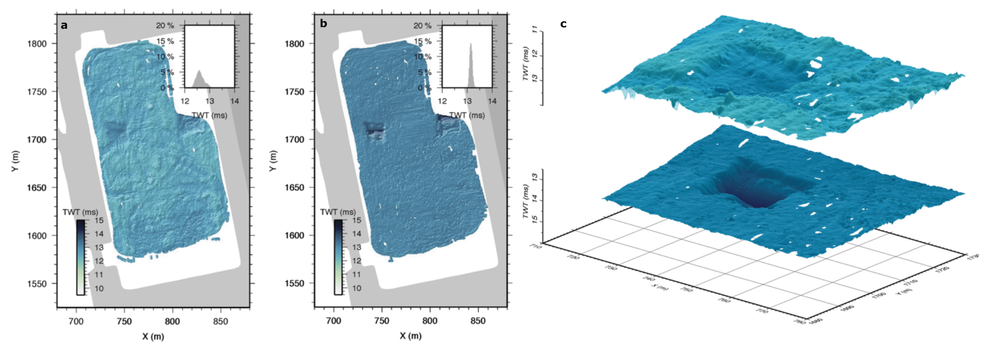
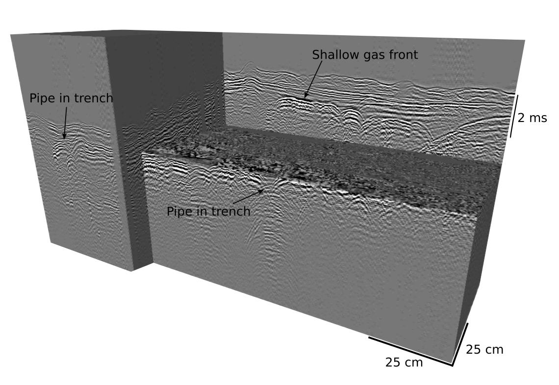
The 3D Chirp was used to survey parts of the UK shelf in water depths ranging from 5 to 25m depth in sands and gravelly sands.
The aim was to image with a consistent penetration to depths to at least 10m below the seabed and to locate all objects larger than 0.25m across to determine their size, depth of burial. The absolute position of each object was also determined to an accuracy of ± 0.1 m using the high accuracy RTK-GPS system built into the 3D Chirp system. This research survey was undertaken ahead of a windfarm installation and focused upon proposed turbine locations (see Figure 1) and other inter-array cable sites. The 3D Chirp was also used alongside magnetometer data to investigate buried UXO targets.
This project demonstrates the capability of the 3D Chirp in the industry sector and its success operating in very low energy protected environments (e.g. harbour basins, lakes or the upper parts of estuaries) to penetrate through finer grained, muddy, substrates. In addition, the unique hydrophone configuration and custom processing algorithms enables full azimuth data and effective 3D migration for object detection.
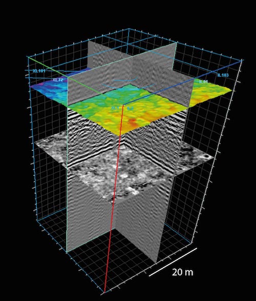
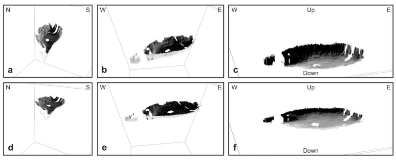
The 3D Chirp has the capability to image complete sub-surface structures. Full, stacked 3D seismic volumes can be generated, normally within 24 hours, using custom in-house sofware to process data incrementally in the field. 3D data has many advantages over individual survey lines.
By sampling the full wavefield, 3D methods produce more coherent images allowing for more intuitive interpretation of complex subsurface geometries and improved post-processing and quality control. Combining horizontal time slices with vertical cross sections it is possible to map the full extent of linear features such as pipes and cables and laterally spanning geological features such as sediment or gas horizons (Figure 1).
The remains of Henry V's flagship, the Grace Dieu (1418), currently lie buried within the inter-tidal sediments of the River Hamble (S. England). Previous archaeological investigations were hindered by difficult excavation conditions resulting in a poor understanding of the dimensions, shape and degradation state of the hull's deeper structure.
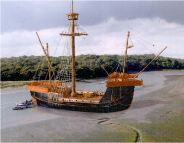
For this case study the 3D Chirp sub-bottom profiler was used to image, characterize and reconstruct the buried remains of this vessel. The accurate navigation and high-resolution data that were acquired enabled the construction of a full 3D image of the site that not only identified the remains of the wooden hull, but also features buried within it.
In addition, the degradation state of these buried wooden remains were investigated by calculating reflection coefficients while a hypothetical larger reconstruction of the Grace Dieu's hull was achieved, through the use of the ShipShape ship design software package.
For more information see Plets et al. (2009); a PDF is available here.