The 3D Chirp has been developed by a multidisciplinary team with specialities including acoustics, seismology and design. Seismic reflection is tool used readily in many industries for sub-surface exploration on many different scales. The key techniques and technologies employed by the 3D Chirp are decribed below, highlighting how imaging at very high resolution is possible.
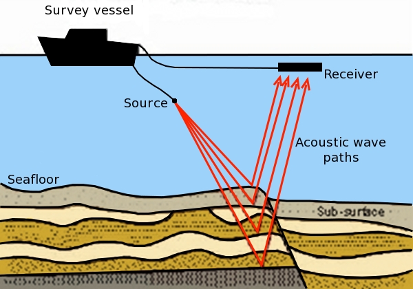
Seismic reflection surveying is a non-invasive technique used to image the geometry of structures and objects in the sub-surface. Artificially generated acoustic waves propagate down through the water column into the subsurface and are reflected from structures and objects that show a contrast in acoustic impedance (Figure 1). These reflected waves are recorded using hydrophones and, after processing of the data, the subsurface can be visualised. These techniques allow structures such as sediment stratigraphy, faults, scours, gas fronts, fluid escape chimneys, and buried objects to be mapped.
The hydrocarbon exploration industry has routinely used marine 3D seismic reflection methods for over 30 years to image geological structures down to kilometres depth with resolution capabilities of some tens of metres with the aim of detecting and mapping the distribution of hydrocarbon traps. However, near-surface high-resolution sub-bottom profiling currently still relies mainly on single-channel 2D methods.
A 2D survey comprises a single line along the water surface, and data is only sampled from seismic waves travelling in one thin vertical plane. However this is not a realistic model given that the goal of seismic surveys is to image as accurately as possible the Earth's sub-surface, which is heterogeneous in three dimensions. Seismic waves travel along expanding spherical wavefronts. A truly representative (or 'photographic') image of the sub-surface is only obtained when the entire wave field is sampled in 3D.
In contrast to 2D methods, which produce individual vertical cross-sections of the subsurface, 3D methods produce data volumes that can be processed coherently across a site, then visualised and interpreted using advanced software revealing the three dimensional geometry of the subsurface. These 3D volumes can be sliced in any direction at any angle, allowing better visualisation and interpretation of complex structures. Respecting the three dimensional wave propagation during data acquisition and processing, 3D seismic reflection data has higher data quality and resolution than 2D data, making it possible to detect small objects and reveal complex geometries.
The basis of the source array of the described technology is the 2D GeoChirp II system, developed by GeoAcoustics Ltd., which uses a four chirp transducer array operating on a bandwidth of 1.5 - 13.0 kHz. This source array produces highly repeatable source signatures that are recorded and correlated with the source sweep to produce high quality seismic reflection data.
New source sweeps have been developed as part of this project that can be chosen depending on the survey target (Gutowski et al., 2002). These new sweeps maximise the active bandwidth of the source waveform, thereby optimising resolution.
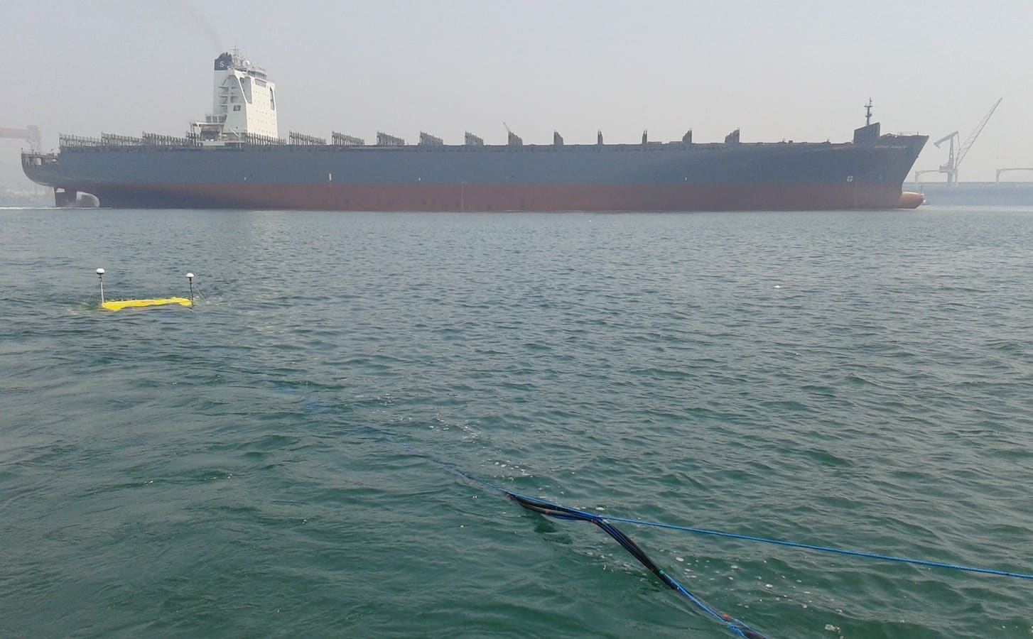
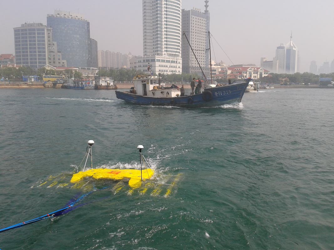
When downscaling the 3D seismic method from typical source frequency ranges of 10s Hz in conventional 3D seismic survey to the kHz range used here, it is essential that the reflected wavefields are fully sampled. In particular it is important that the receiver spacing is adapted to the frequency range, to avoid spatial aliasing, and to adequately record the absolute positions of the source and receiver elements during data acquisition. To achieve these, the design concept used in the 3D Chirp profiler described here, is to place all source and receiver elements on a rigid structure with a receiver spacing of 25 cm that is positioned using Real Time Kinematic GPS technology (RTK-GPS). This samples the reflected wavefield at 12.5 cm intervals and positions each source and reciever pair to an accuracy of X= ±0.46 cm, Y= ±0.70 cm, and Z= ±1.82 cm (Bull et al., 2005).
On the 3D Chirp array, the hydrophone receivers are mounted in the underside of the array, and far more than for a normal 2D system. To fully sample the reflected wavefields in 3D, these hydrophones are not confined to a single line, rather they form a 2D grid. Thereby these multiple hydrophones receive the signals along many different directions or azimuths and offsets. A normal 3D survey produces offsets that are collected about 360° of azimuth so that the powerful resolution improving and geometry correcting data processing algorithm called 3D migration can be applied. Images and further details on the configuration of the 3D Chirp array can be found with the full specification.
The resolution of seismic data can be improved substantially by a process called migration. As illustrated in Figure 4 (French, 1974), this process is greatly enhanced when used with 3D data over 2D data. French produced synthetic seismic sections from a model with 2 anticlines (yellow and green 'domes'; Figure 4) and a fault scarp (red feature; Figure 4). Thirteen seismic 2D sections were produced, the results of which are only shown for Line 6. The raw data shows diffraction patterns for both anticlines and the fault, so the section is confusing and also inaccurate. The image is improved with 2D migration: Anticline 1 (green) is correctly imaged as line 6 passes over its crest. However Anticline 2 (yellow) is not beneath Line 6, and the fault scarp has the wrong slope. In the 3D migration, the fault scarp is correctly imaged and the section does not include the yellow anticline. This model is for a relatively simple case, in near-surface sediments there can be rapid variation in physical properties, and for the correct positioning of objects and layers 3D migration is essential.
Because the 3D Chirp system described in these webpages fully samples the reflected wavefield it is a true 3D system. This allows 3D Chirp data volumes to be processed using 3D migration, unlike systems describing themselves as Pseudo3D or 2.5 D (which rely on closely spaced lines for correct positioning of layers and objects). A new approach to pre-stack 3D Kirchhoff time migration has been developed as part of this project, which permits imaging in near real-time (Vardy and Henstock, 2010).