3D Chirp Specification

wireframe3DC_top
wireframe3DC_bottom

Summary

The 3D Chirp is a sub-bottom profiler developed jointly by the University of Southampton and Kongsberg GeoAcoustics. The system is neutrally-buoyant and can be surface-towed either alongside or a short distance behind a vessel of opportunity.

60 hydrophone groups are distributed in a 25.0 x 25.0 cm spaced grid around a central source array of 4 Chirp transducers. This permits full azimuthal coverage in 3D with a theoretical mid-point bin size of 12.5 cm with regular sampling in both along- and across-track directions.

The array has a 3-part modular design that allows for quick assembly and deployment on-site as well as efficient transportation.

A range of custom, programmable Chirp source sweeps have been developed to provide decimeter-resolution, in marine sediments. Through many applications, this system has proven vertical resolution < 10 cm and penetration of > 30 m in fine-grained silts/clays, 5 – 10 m in coarse-to-medium sands, and 5 – 10 m in mudstone/siltstone/limestone sequences. (More information on the primary 3D Chirp sweep can be found here.)

True 3D Seismic Imaging

Construction:
Dimensions:
  • 3 x 2 m
Source Array:
  • 4 Chirp transducers arranged in a Maltese Cross
Source Waveform:
  • 1.5 – 13.0 kHz broadband Chirp sweep
  • Up to 8 Hz shot-rate
Receiver Array:
  • 60 hydrophones groups
  • 25 cm spacing (inline and crossline)
Typical Resolution:
  • Vertical: < 10 cm
  • Horizontal: 37.5 cm
Typical Operation:
Water Depths:
  • < 5 m to at least 80 m (maximum to date)
Survey Speed:
  • 3 – 5 knots
Survey Areas:
  • Several 100s m2 to
    c. 150,000 m2
Processing Workflow:
  • Real-time data QC
  • Near real-time NMO- stacked volumes
  • Pre-stack Kirchhoff time migration imaging
Navigation:
Normal Accuracy:
  • 1-2 cm horizontal and vertical
Absolution Position:
  • RTK-GPS with post- processed base station surveying
Relative Source and Receiver positions:
  • Dual-antenna RTK-GPS heading
  • Motion reference unit (MRU) attitude measurements

3D Chirp Sweep

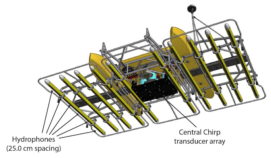
The source waveform for the 3D Chirp is a linear, 16-millisecond Chirp between 1.5 – 13.0 kHz. This is transmitted from an array of four transducers in the centre of the 3D Chirp.

This short sweep is very repeatable and permits shot-rates up to 8 Hz, allowing high fold-of-coverage to be obtained with a single pass and normal tow speed of 3 kn.

waveform7 sweep image

Spanning more than 3 octaves, this custom broadband sweep makes decimetre-resolution imaging possible. The autocorrelation Klauder wavelet (bottom left) is zero phase with a peak-side lobe distance of 0.06 ms. Combined with a high-performance navigation system traces can be stacked coherently and clean subsurface reflections and hyperbolae can be interpreted in processed 3D Chirp data.

waveform7 wavelet image

Data Processing

The 3D Chirp writes standard-compliant IEEE SEG-Y files for processing using both custom and off-the-shelf software. Several bespoke workflows/software have been developed at the University of Southampton permitting advanced processing of 3D Chirp datasets:

Specification PDF

A PDF version of the 3D Chirp specification can be downloaded here.